Information
Our indoor positioning system TPC_IPS Ver1.0 was released on April 1, 2022.We also plan to release IPS application templates "QuickIPS" and "TPC_IPS Web API" which allow interactions with external IPSs/RTLSs in the future.
- What is IPS?
- IPS User Application with FileMaker
- Typical User Applications
- QuickIPS Demo Video
- Why FileMaker?
- Floor Map Using Scatter Graph
- Floor Map Using Objects
- Heatmap Using Objects
- Error Graph
- About The Basic Operation of QuickIPS
- Three Modes: AUTO, MANUAL and HISTORY
- Header Part
- Picker Floating Window
- Error Summary Floating Window
- Use on iPhone/iPad
- Integrating QuickIPS with An External System
- About Customizing QuickIPS
- IPS Related Blog Posts
What is IPS?
We have been developing a system called TPC_IPS. In a nutshell, IPS (Indoor Positioning System) can be described as an indoor GPS; a system that grasps the positions of people and things indoors. If the environment is indoors or underground, positioning is impossible with satellite technology like GPS, and positioning accuracy will not be satisfactory, so IPS performs indoor positioning. IPS is also one of the IoT (Internet Of Things) technologies.

The image above is an overview of IPS in a warehouse. Transmitters called beacons or tags are attached to people or things, the receiving terminals (![]() ) read the signals (
) read the signals (![]() ) emitted by those beacons, and finally the computer analyzes the signal information in order to measure the positions of individual beacons. This positioning information can be referenced by internal or external users via the LAN/WAN. Such an IPS that administers many things as shown in the image below is sometimes called an Asset Tracking system.
) emitted by those beacons, and finally the computer analyzes the signal information in order to measure the positions of individual beacons. This positioning information can be referenced by internal or external users via the LAN/WAN. Such an IPS that administers many things as shown in the image below is sometimes called an Asset Tracking system.
IPS User Application with FileMaker
The following figure is an IPS configuration example. In this example, the IPS is divided into two subsystems: Positioning and User Application. Positioning literally calculates the coordinates of individual beacons. As of May 2021, our product TPC_IPS, uses BLE4 beacons for positioning; however, UWB which was recently adopted by AirTag is gaining attention. USB products for IPS/Asset Tracking which are not limited to mere lost-and-found tags are expected to appear on the market in the upcoming years.
Note:
UWB IPS products such as Ubisense and Zebra have been available from some time ago, however, only some large companies have adopted them because they are quite expensive. The advent of AirTag and SmartTag may contribute to the widespread adoption of low-cost UWB IPS.
We have already posted the positioning using TPC_IPS before (see the link at the end), so in this article we are going to give you an overview of our -QuickIPS- user application template using FileMaker.
Note:
QuickIPS will be bundled with TPC_IPS. The standalone version will be released later this year.
* QuickIPS specifications and schedule are subject to change without notice.

Note:
The above diagram shows how a server computer performs positioning of beacons and tags attached to objects. This method is used for Asset Tracking (or Asset Management). Another way to achieve indoor positioning in a more GPS-like fashion is for a mobile app (device) to track its own position within a grid of fixed beacons and tags.
Typical User Applications
The previous diagram describes the flow that each beacon or tag sends its information to the server computer, the server computer calculates the location information based on the collected information, and the database stores the result location information along with the beacon IDs (or tag IDs).
Furthermore, the user application accesses the location data in the database to process the data according to user's preferences, and display the results on the computer or the smartphone. The following are three typical user applications.
- Floor map - displays the positions of people and things on a floor map
- Heatmap - displays the degree of congestion of people
- Motion tracking - represents the consecutive movements of a person or a thing as a line
Of these, 1 and 2 can be developed in FileMaker alone. QuickIPS is a user-customizable template that implements these two.
The object tracking feature will be included in future versions of QuickIPS and TPC_IPS. Please read this post in out blog for more information on object tracking.
QuickIPS Demo Video
Here is an 11 minute QuickIPS overview video.
Turn on CC to see English subtitles.
Why FileMaker?
The reason is simple. FileMaker requires less man-hours than other tools to create a graphical application. FileMaker is also suitable for prototyping IPS user applications. The following is a detailed introduction to the QuickIPS features.
Floor Map Using Scatter Graph
The figure below is a floor map that displays the beacon positions using FileMaker's scatter graph feature. A map (an image file) for plotting location information is imported in the background of the FileMaker layout in advance, and a scatter graph is placed over the map.
The advantages of this method are rounding coordinates data (described later) is not required, and it is easy to create; however, this map also has disadvantages such as the beacon names may overlap when multiple beacons are detected in close proximity, and detailed beacon information cannot be desplayed.
|
| The beacon names overlap when multiple beacons are detected. |
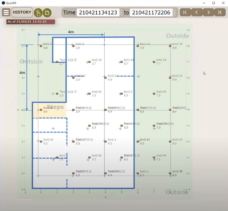
Floor Map Using Objects
In this method, SVG spot icons (![]() ) and beacon information objects are placed at the coordinates (fixed point coordinates) predetermined by the user, whereas the information of the positioned beacon is displayed by these beacon information objects.
) and beacon information objects are placed at the coordinates (fixed point coordinates) predetermined by the user, whereas the information of the positioned beacon is displayed by these beacon information objects.
Unlike the scatter graph method, you can fine-tune this feature; multiple beacons on the same coordinates can be displayed, while those beacons which positions are different from the actual coordinates can be displayed in red, and the display font size can also be changed (using ◀ A ▶).

|
|
|
"Rounding" of Position Coordinates With an External System
TPC_IPS's Positioning feature can calculate the beacon coordinates by rounding the measured coordinates to the fixed point coordinates.
However, if you wish to use QuickIPS with an external system, you need to do this rounding on the external system.
Example:
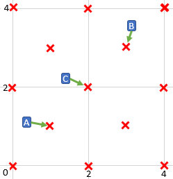
You have set the fixed point coordinates ( x ) as shown in the figure below. Then, the external system detects the beacons as follows. The x and y coordinates are shown in parentheses.
|
Beacon A (0.2, 1.1)
Beacon B (3.2, 3.6)
Beacon C (1.5, 2.1)
Suppose the closest fixed point coordinates (x) to each positioning coordinate are determined as the coordinate of each beacon (this is the rounding process). In this example, beacon A (0.2, 1.1) is rounded to the fixed point coordinate (1,1), beacon B (3.2, 3.6) is rounded to (3, 3), and beacon C (1.5, 2.1) is rounded to (2, 2) respectively.
Note:
You may code your own program to find the closest fixed point coordinates (the nearest neighbor points), but if you can use K-nearest neighbor (k = 1) libraries, you can achieve it quite easily. It may be possible to create a knn custom function in FileMaker and apply it to the rounding process when retrieving data from an external database, however, it will be quite difficult.
Even that famous Brian Dunning's custom function publishing site has not shared any knn custom functions so far.
TCOT (Two-Circle Oriented Trilateration), the positioning algorithm in TPC_IPS, calculates the coordinates with a trilaterational approach, so that the raw positioning coordinates do not almost always match the fixed point coordinates. For this reason, when executing TCOT, KNeighbors of scikit-learn provides an option to round to fixed point coordinates.
By nature of trilaterational approaches, there is a certain degree of errors from the fixed point coordinates. To correct such deviations, we provide an option to use the KNeighbors algorithm of scikit-learn to round coordinates to the closest fixed coordinates during the TCOT process.
Heatmap Using Objects
Heatmap displays the state of many people and things in the same place in different colors. Heatmap also requires rounding position coordinates.

|
| The density of people and things is displayed in the order of blue, yellow, and red. |
Error Graph
Error graph displays the errors between the actual coordinates of the beacons in a stationary state and the positioning coordinates as a line graph. This feature is useful for positioning system engineers to check the accuracy of positioning.

|
| The horizontal axis is the scanning time, the vertical axis is the error; the smaller the error value, the higher the positioning accuracy. |
When the beacons to be displayed on the graph is selected from the picker floating window (described later), the positioning error is displayed on the vertical axis within the time range specified by [Time].
During the test before operating an IPS, this feature becomes useful for checking whether the positioning accuracy that suffices the operation. In addition, the accuracy of positioning varies due to changes in the indoor environment, so use this feature in a timely manner to check the positioning accuracy.
Note:
When the automatic update button ● is running in AUTO mode, or the update button ![]() is clicked in MANUAL mode, the error graph is updated with the latest positioning information.
is clicked in MANUAL mode, the error graph is updated with the latest positioning information.
About The Basic Operation of QuickIPS
This section explains basic operations of QuickIPS.
Three modes: AUTO, MANUAL and HISTORY
QuickIPS has three operational modes: AUTO, MANUAL, and HISTORY. Each mode is selected from the pull-down menu by clicking "Execution mode" in the figure below.
AUTO Mode
● button will be displayed in the upper right corner of the screen. Click it to automatically update the Floor map, Heatmap, and Error graph with the latest data. Click ■ to stop automatic update.
MANUAL Mode
This mode, unlike AUTO mode, does not update the information automatically. To update with the latest information, click ![]() displayed in the upper right corner of the screen.
displayed in the upper right corner of the screen.
HISTORY Mode
In this mode, Floor map, Heatmap, and Error graphs can be displayed based on the past coordinate data.
Header Part
This section explains how to use the header part at the top of the screen.

| Submenu button |
Click to display the pop-up menu. Select from the following menu items:
Scatter map (floor map using scatter graph)
Floor map (floor map using objects) Heatmap Error graph (distance error graph) |
| Execution mode |
Select from AUTO, MANUAL, and HISTORY described earlier. |
| Time |
Specify the range of ScanCode (date and time when the scan was executed in YYMMDDMMDDSS format). Note: ScanCode is automatically generated by TPC_IPS. |
| ScanCode navigation |
Buttons for moving/selecting between ScanCodes within the range specified in [Time] |
| Picker button | Display a picker/floating window (described later) for selecting the target beacon and ScanCode. |
| Error summary button | Display the error summary floating window (described later) that displays the details of the positioning error. |
Picker Floating Window
This window is used for selecting the target beacon(s) and ScanCode in the Floor map, Heatmap, and Error graph. This window is always in the foreground until it is closed with the x button.
| Beacon list | List of beacons. Click to select or deselect. The selected beacons are displayed in pink. The selected beacons will be displayed on the Floor map. Up to six beacons can be displayed in the Error Graph. |
| Beacon name format |
Click to switch the format of the beacon name displayed on the floor map. |
| All button | Select all beacons |
| None button | Deselect all beacons |
| ScanCode list | A list of ScanCodes within the range specified by [Time]. Click to select and the floor map and heatmap will be displayed based on the coordinate data with that ScanCode. |
Error Summary Floating Window
The error summary floating window displays a summary of the positioning errors of the selected beacon(s) from the picker floating window. The line chart of the error graph can display up to 6 beacons at a time, but there is no limit to the number of beacons that can be selected in this summary.
This window is always in the foreground until it is closed with the x button.
| Positioning error summary | The positioning error of the beacons in the stationary state is displayed for each beacon. Displays the average, maximum, minimum, and standard deviation of the positioning error of the beacon selected from the beacon list. The last line shows the aggregated value of all selected beacons. The aggregation target is the time range specified in [Time]. |
| Error type |
The buttons for selecting the type of error and the error calculation formula when each button is selected are as follows: |
Use on iPhone/iPad
Two types of Floor maps, Heatmap, and Error graph features are also available on iPhone/iPad (iOS). These screens use the same screens as those for PCs, so that cost-effective development will be possible.

|
| You need to take an extra care on PC/iOS representation when developing an IPS application |
Integrating QuickIPS With an External System
QuickIPS has a table called locLog that stores coordinates data; the data in locLog is retrieved and processed for the QuickIPS features described earlier.
If the database on the external system has a table or view that is compatible with locLog, then the data can be imported into locLog table for QuickIPS.
locLog Table Structure
When using QuickIPS with an external database other than TPC_IPS, create a table based on the QuickIPS locLog table schema.
| Field name | Data type | Input | Remarks |
|---|---|---|---|
| uuid | text | Mandatory |
Beacon uuid |
| major | numeric | Mandatory | Major assigned to the beacon |
| minor | numeric | Mandatory | Minor assigned to the beacon |
| beaconName | text | Beacon name, required for displaying beacon information | |
| x | numeric | Mandatory | X coordinate of the positioned beacon |
| y | numeric | Mandatory | The y coordinate of the positioned beacon |
| actual_x | numeric | The actual x coordinate of the beacon [Note 1] | |
| actual_y | numeric | The actual y coordinate of the beacon [Note 1] | |
| scanCode | numeric | Mandatory | 12-digit number representing the scan time stamp (YYMMDDHHMMSS) [Note 2] |
| timestamp | timestamp | Date and time the record was created |
- actual_x and actual_y are the coordinates of the actual beacon used during the positioning accuracy test. The positioning error is calculated using these values and the measured coordinate values.
- When using QuickIPS, a scanCode generated for each scan is required. When generating scanCode on an external system, make sure that each sensor executes the scan at the same timing, and set the same value (YYMMDDHHMMSS) to scanCode for each scan. For example, when the beacon/tag signal is scanned at 2022/1/1 0:0:0, "220101000000" is stored to the scanCode of each record on the server etc. regardless of the clock of the sensor/receiver.
Importing Data From an External Database into QuickIPS locLog Table
The external table data as described above can be imported into QuickIPS locLog table in the following manner:
- Register the given DSN with the ODBC driver for the external database on the computer running QuickIPS
- Specify the table name to be fetched and the field names of the external table corresponding to the locLog table.
- Perform data import using External Data Import screen
About Customizing QuickIPS
The floor map using objects mentioned earlier can be customized as described in the figure below.
SVG spot icons and the beacon information objects (painted in pink in the figure for visibility, but they are actually transparent) have coordinate attributes respectively, so they need to be placed according to the coordinate attributes. For example, the object of the coordinate (2, 8) needs to be placed at coordinate (2, 8) on the floor map.

When creating a floor map for a large facility, the floor map image needs to be splitted, so that those floor map images will be imported on the newly created multiple layouts, tabs, and slides respectively.
QuickIPS will be released separately from TPC_IPS as a FileMaker template.
* QuickIPS specifications and schedule are subject to change without notice.
IPS Related Blog Posts
- IPS Application Templates for FileMaker ― QuickIPS ―*
- Indoor Mobile Position Monitoring Model with iBeacon/Raspberry Pi 1 ― Overview*
- Indoor Mobile Position Monitoring Model with iBeacon/Raspberry Pi 2 ― RSSI/Distance Calibration and Trilateration*
- Indoor Mobile Position Monitoring Model with iBeacon/Raspberry Pi 3 ― Enhancement of Two-Circles-Oriented Trilateration (TCOT) and Measurement Results*
- Estimate the approximate position of the beacon with a small number of receivers in a large area such as Tokyo Dome(Google translate)
- Improving IPS Positioning Accuracy with Machine Learning *
- TIPS for making IPS testbeds(Google translate)
- Object Tracking for Visualizing The Movements of People and Objects on a Map*
- Send Location Information via UDP - TPC_IPS/QuickIPS Extension*
- * indicates that original article translation into English has been completed by TPC.
- "Google translate" indicates that clicking it will Google translate the original article, and may be translated into English in the near future by TPC.
No comments:
Post a Comment